Shanghai, China
+86-17317656853
inquiry@cgprotection.com

Arc flash, a type of electrical explosion, is one of the most complex workplace risks that exist. It is often described using technical terminology and acronyms. Also, several basic concepts and definitions are key to understanding how arc flash hazards are measured and how this information can be used to help protect personnel. Below are the most important ones with simple explanation.
This is the amount of thermal incident energy to which the worker's face and chest could be exposed at working distance during an electrical arc event. Incident energy is measured in joules per centimeter squared (J/cm2) or calories per centimeter squared (cal/cm2). Minimum reported incident energy is 0.25 cal/cm2 which is the accuracy limit of the test equipment.
A value in cal/cm^2 to determine arc flash boundary (AFB) distance at that Incident Energy. The Incident Energy of 1.2 cal/cm^2 for bare skin is used in solving equation for arc flash boundary in IEEE 1584 Guide for Performing Arc Flash Hazard Calculations. However, the Guide equation for arc flash boundary can be solved with other incident energy levels as well such as the rating of proposed personal protective equipment (PPE). The Incident Energy at Arc Flash Boundary value should be equal or above incident energy to second degree burn for bare skin exposure.
The arc flash boundary is an approach limit at a distance from exposed live parts or enclosed live parts if operation, manipulation, or testing of equipment creates a potential flash hazard, within which a person could receive a second degree burn if an electrical arc flash were to occur. A worker entering the arc flash boundary must be qualified and must be wearing appropriate PPE. The arc flash boundary is required to be calculated by NFPA 70E.
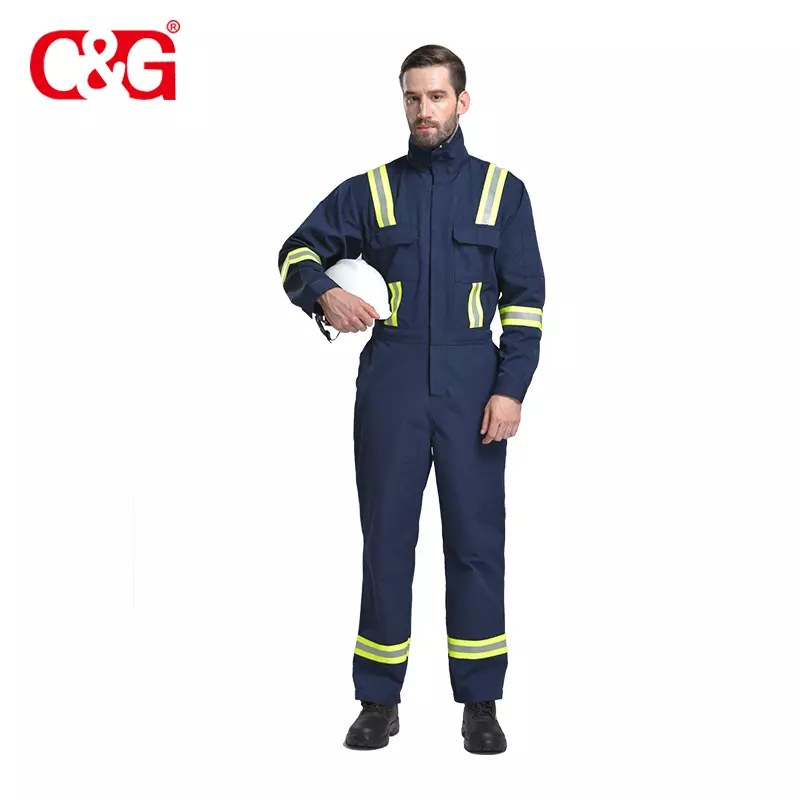
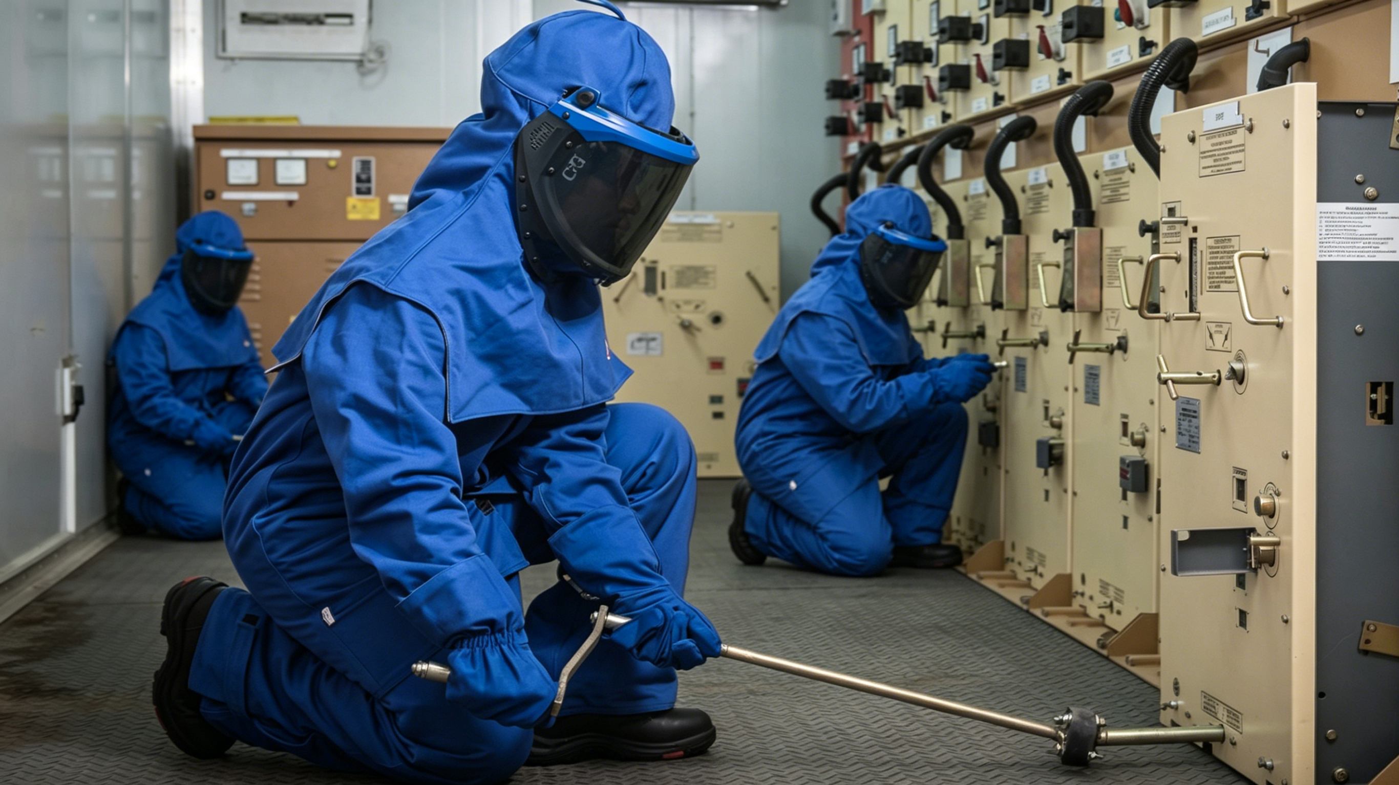
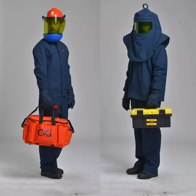
C&G Safety 67cal arc flash protective coverall
This is the minimum level of Personal Protective Equipment in calories per centimeter squared, as evaluated in IEEE Standard 1584, with the intent to protect the worker from the thermal effects of the arc flash at working distance from the source of the arc.
| Min Incident Energy, cal/cm^2 | Max Incident Energy, cal/cm^2 | Hazard Level | Required Min Rating of PPE, cal/cm^2 |
| 0 | Eb | 0 | |
| Eb + 0.001 | 4 | 1 | 4 |
| 4.001 | 8 | 2 | 8 |
| 8.001 | 25 | 3 | 25 |
| 25.001 | 40 | 4 | 40 |
| 40.001 | and above | Consult | Not Available |
| Hazard Level | Personal Protective Equipment ( PPE ) |
| 0 | Untreated natural fiber long sleeve shirt & pants with a fabric weight of at least 4.5 oz/yd^2, safety glasses, ear canal inserts, heavy duty leather gloves. |
| 1 | Arc rated (AR) shirt and AR pants or AR coverall, AR face shield, AR jacket, safety glasses, hard hat, ear canal inserts, heavy duty leather gloves, leather footwear. |
| 2 | Arc rated (AR) shirt and AR pants or AR coverall, AR flash suit hood, AR jacket, safety glasses, hard hat, ear canal inserts, heavy duty leather gloves, leather footwear. |
| 3 | Arc rated (AR) coverall over AR shirt and AR pants, AR flash suit, AR hood, safety glasses, hard hat, ear canal inserts, AR gloves, leather footwear. |
| 4 | Multilayer arc rated (AR) flash suit over AR coverall over AR shirt and AR pants, AR flash suit hood, safety glasses, hard hat, ear canal inserts, AR gloves, leather work shoes. |
Classes of equipment included in IEEE 1584 and typical bus gaps are shown in table below:
| Classes of equipment | Typical bus gaps, mm |
| Open Air | 10 - 40 |
| Low-voltage switchgear | 32 |
| 15kV switchgear | 152 |
| 5kV switchgear | 104 |
| Low-voltage MCCs and panelboards | 25 |
| Cable | 13 |
Equipment bus gap in mm. Gaps of 3 to 40 mm were used for low voltage testing to simulate gaps between conductors in low voltage equipment and cables. Gaps 13, 104 and 152 mm. were used in 5 and 15kV equipment testings.
Two grounding classes are applied in the IEEE 1584 procedure, as follows:
a) Ungrounded, which included ungrounded, high-resistance grounding and low-resistance grounding.
b) Solidly grounded.
Typical working distance is the sum of the distance between the worker standing in front of the equipment, and from the front of the equipment to the potential arc source inside the equipment.
Arc-fash protection is always based on the incident energy level on the person's face and body at the working distance, not the incident energy on the hands or arms. The degree of injury in a burn depends on the percentage of a person's skin that is burned. The head and body are a large percentage of total skin surface area and injury to these areas is much more life threatening than burns on the extremities. Typical working distances are shown in table below:
| Classes of equipment | Typical working distance, mm |
| Low-voltage switchgear | 610 |
| 15kV / 5kV switchgear | 910 |
| Low-voltage MCCs and panelboards | 455 |
| Cable | 455 |
Use protective device characteristics, which can be found in manufacturer's data. For fuses, the manufacturer's time-current curves may include both melting and clearing time. If so, use the clearing time. If they show only the average melt time, add to that time 15%, up to 0.03 seconds, and 10% above 0.03 seconds to determine total clearing time. If the arcing fault current is above the total clearing time at the bottom of the curve (0.01 seconds), use 0.01 seconds for the time.
For circuit breakers with integral trip units, the manufacturer's time-current curves include both tripping time and clearing time.
For relay operated circuit breakers, the relay curves show only the relay operating time in the time-delay region. For relays operating in their instantaneous region, allow 16 milliseconds on 60 Hz systems for operation. The circuit breaker opening time must be added. Opening times for particular circuit breakers can be verified by consulting the manufacturer's literature.
Available 3 phase bolted fault current for the range of 700A to 106kA at the point where work is to be performed is entered into this box in kA. Example: if 42,350 amps are available, enter 42.35 into this box. If 16,000 amps are available, enter 16 into this box.
System Line to Line Voltage for the range of 208V to 15000V.
For protective devices operating in the steep portion of their time-current curves, a small change in current causes a big change in operating time. Incident energy is linear with time, so arc current variation may have a big effect on incident energy. The solution is to make two arc current and energy calculations; one using the calculated expected arc current and one using a reduced arc current that is 15% lower.
Tags:

Shanghai C&G's personal protective clothing and PPE products are trusted by customers in the world. Our products are exported worldwide, with a strong presence in the United States, China, Japan, Germany, the United Kingdom, India, France, Italy, Brazil, and Canada. In addition, we have a significant customer base in other countries across each continent, including Australia, New Zealand, South Africa, Nigeria, and Egypt in Africa; Argentina, Chile, and Mexico in South America; Russia, South Korea, and Indonesia in Asia; Spain, Poland, and Turkey in Europe; and Saudi Arabia and the United Arab Emirates in the Middle East. Wherever you are in the world, we have the products you need to stay safe and protected. Contact us today to learn more about our products and how we can help you meet your safety needs.


Shanghai C&G is committed to building a leading brand in the safety emergency industry with technological innovation as the core and sustainable development, providing customers with one-stop safety emergency solutions, escorting the safety of customers, and make the world safer!
Building 39, Lane 123, Shenmei Road, Pudong New District, Shanghai, China
inquiry@cgprotection.com
+86-21-38214394


© 2023 Shanghai C&G. All Rights Reserved.